Quantcast
Channel: Products – Thonk – DIY Synthesizer Kits & Components
Viewing all 2274 articles
Browse latest View live

Music Thing Modular – Simple EQ – Full Kit

$
0
0

Simple EQ –  Learn SMD soldering by building two channels of the kind of tone controls you’d find on an old hifi. No voltage control, but just enough range to push sounds into distortion. Works well in a feedback loop.

SMD soldering is not recommended for complete beginners! Make sure your soldering iron has a good fine tip before attempting this build. A flux pen is also recommended.

Build docs, BOM etc – https://thonk.co.uk/documents/simple-eq-kit/

PCB
kitopenkit


Fonitronik – Ps3100 Triple Vactrol Resonator – FULL DIY KIT

$
0
0

Full DIY Kit. Everything you need to build right down a complete module right down to the screws and power cable. You just provide the tools, time and solder.

Please note we are not providing a Thonk build document for this build, but it’s a simple enough build with no wiring and the Fonitronik documentation is very good.

What we have here is basically a module combining three bandpass filters (vactrol based filter core from the PS3100) with a simple resetable LFO and some clever CV and signal routing.

The module provides
– 3 single audio inputs + a common audio input,
– 3 single audio outputs + sum audio output
– 3 single CV inputs with attenuators + a common CV input
– LFO output, LFO reset input

The LFO is normalled to the common CV input, which is normalled to the 3 single CV inputs. the 3rd CV channel can be inverted.

I Dream Of Wires – Hardcore Edition – Documentary

$
0
0

Hardcore Edition – Extended Cut – 4 hours in length.

REGION FREE – Will play in any region.

“I Dream of Wires” (IDOW) is an independent documentary film about the phenomenal resurgence of the modular synthesizer — exploring the passions, obsessions and dreams of people who have dedicated part of their lives to this esoteric electronic music machine. IDOW is written and directed by Robert Fantinatto with Jason Amm (Ghostly Internationalrecording artist Solvent) serving as producer and co-writer.

Inventors, musicians and enthusiasts are interviewed about their relationship with the modular synthesizer — for many, it’s an all-consuming passion. Established musicians such as Trent Reznor (Nine Inch Nails), Carl Craig and John Foxx show off their systems and explain why they opt to use this volatile but ultimately rewarding technology. Meanwhile, a new generation of dance and electronica artists including Clark, James Holden and Factory Floor explain why they’ve stepped away from laptops to embrace the sound and physicality of modular synthesizers. Innovative companies like Modcan and Doepfer, driven by a desire to revive modular synthesizers, discuss how they planted the seeds that have now grown into a major cottage industry. What started out as a “vintage-revival scene” in the ’90s has grown into an underground phenomena with a growing market of modular obsessives craving ever more wild and innovative sounds and interfaces. Today, the modular synthesizer is no longer an esoteric curiosity or even a mere music instrument — it is an essential tool for radical new sounds and a bonafide subculture.

http://www.idreamofwires.org/

IDOW


Buchla Dual Function Generator 281 – Barcode/Toppobrillo Panel and PCB

$
0
0

This set includes:

  • Barcode 14hp Black Eurorack Panel
  • Barcode Panel PCB (for pots jacks etc)

Optionally you can include:

  • Toppobrillo 281 PCB (required for all builds)
  • Pots (required for all builds)
  • Jacks (required for all builds)

281-Daughterboard-photo


Toppobrillo 281 Documentation Bundle – BOM,

~A DIY PROJECT BASED ON BUCHLA MODEL 281 QFG~

Current Consumption

(@+/-15V) around +15mA (slightly more with LED); -10mA maximum per FG

The PCB is 76mm by 107mm.

 This Toppobrillo PCB is a dual function generator. Two AD envelopes with extensive CV control. It can run on both +/-15v or +/-12v (with some resistor changes noted in documentation).

The Original Buchla 281 Module is made up of 4 independent Function Generators, A,B,C and D- with A&B and C&D tied together in the bottom section functions, quadrature and ors [peak]. The 281 Clone PCB is actually half of a 281, and can be used alone or in conjunction with other boards.

The 281 Function Generator

…Operates like most envelope generators, it’s operation is as follows: An appropriate signal at the trigger input causes the generator to ramp upwards from 0 to 10V at a rate set by the “attack” control and input. Depending on operation mode, once it reaches 10V, it is either held steady by a gate signal, pending release, or enters the decay phase instantly [depending on operation mode] and then ramps downward towards 0V at a rate specified by the setting of the “decay” control and input. At any point in the “decay” cycle, the generator can be retriggered. Once the cycle is complete, the “end pulse” output will produce a narrow pulse.

The output function is linear, however, the rate [slope] responds to applied control voltage in an exponential manner. Applied positive voltages will cause the generator to ramp more slowly- while voltages that are less positive than the voltage at the control pot’s wiper will cause the generator to ramp more quickly. These voltages average together.

Modes of Operation

“Gate” or “sustain” mode (ASR): when the attack phase is complete, the generator will not enter the “decay” phase until the “trigger” input goes low. Note that just about any signal that meets or exceeds the input comparator’s threshold (around +5V) will fire/sustain the FG.

“Transient” mode (AR): when the attack phase is complete, the generator enters the decay phase, regardless of the status of the “trigger” input. Note that operation in this mode requires that the “trigger” input be one that has a relatively fast low-to-high transition, such as a pulse/square \wave, or perhaps an inverted saw-tooth. The trigger threshold is around +5V built as shown.

“Cycle” mode (LFO): when the decay phase is complete, the generator will retrigger itself. The cycle mode can be configured to respond to the “trigger” inputs as either “transient” or “sustain” modes.

Quadrature and Peak Functions

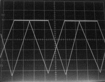
“Quadrature” mode: When this is selected, two generators are linked together in a loop configuration so that FG “B” will be slaved to “A”. This operation is as follows: FG “A” reaches it’s peak, FG “B” then begins to cycle, while “A” won’t enter it’s decay phase until “B” completes it’s attack; then, “B” will sustain until “A” ends it’s decay phase, at which time “B” begins to decay.

This process is illustrated below:

Depending on the attack and decay times, the resulting relationship can maintain an approximate 90 degree separation of phase between the 2 functions. When the two function’s cycles are of similar length, the resulting waveforms are trapezoidal.

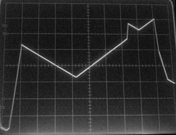
“Peak” section: The Peak (called “OR” in the original module) section used here is a discrete TTL “OR” gate. I don’t know what this section in the original Buchla circuit looks like, but this one works pretty well. It’s output, at any given time, is the maximum, or peak of it’s input voltages.

This process is illustrated below:

In the 281, the “A” function is input unattenuated, while the “B” function has an attenuator on it’s input. This allows the for the creation of complex envelopes between them. It is easy to add additional inputs to this simple circuit if it is desired.

End Pulse

the narrow “end pulse” occurs at the end of a cycle. Note that this output pulse-transient can be large- on the order of +15V in amplitude (used w/15V PSU). This of course can be attenuated if this is thought to pose any problems with other circuitry.


Ginkosynthese – TTLFO v2 – Full DIY Kit

$
0
0

This is the upgraded version of the TTLFO available as DIY kit.It can go wild! All parameters are voltage controlled and modulating the waveform, clock divider or distort function gives you the most exciting waveforms you can imagine, but all in sync with your clocksignal.

It is a relatively easy build but has quite a lot of parts. So it is suitable for beginners but building will take about 2 hours (you can probably do it faster but you need to enjoy it).

  • Eurorack size
  • Width: 8HP
  • +/-12V (no 5V needed)
  • compatible with Doepfer
  • skiff-friendly (only 25mm in depth)

Features

  • 8 waveforms
  • multiplier / clock divider
  • horizontal wave distort
  • external clock input
  • CV input for waveform select
  • CV input for multiplier
  • CV input for distort amount
  • LFO output (selectable between 0/5V and -5V/+5V)
  • clock output

Technical info

Module width
8HP
Module depth
25mm
Power use (+12V)
35mA
Power use (-12V)
10mA

 Build Manual – http://www.ginkosynthese.com/uploads/MANUAL.pdf

Ginkosynthese – Grains – Full DIY Kit

$
0
0

A DIY eurorack module! This complete and easy-to-build DIY kit is one of the cheapest ways to get a voltage controlled oscillator in your modular and sounds completely different than all other oscillators! It can do minimalistic clicks and plops, screaming leads, fat basslines, weird noises or chiptunes.

This is a DIY kit

The kit includes:

  • PCB
  • Aluminium frontpanel
  • all electronic parts
  • Knobs and jacksockets
  • Arduino
  • powercable

How it works
The sound is a PWM output routed via an (optional) low-pass filter and a 100uF capacitor – so no external DAC is required. The low-pass filter on the PCB can be bypassed if you want. Bypassing the filter provides more clarity and a slightly louder output but more artifacts in the sound.

Not bored yet?
Here comes more information about the synthesis technique on the basic code and you will understand why I called this module “Grains”.
The “Grains” code provided on your module is based on FOF synthesis or formant synthesis. FOF synthesis is closely related to synchronous granular synthesis. It uses two simple triangle-shaped grains. The grains are separated by the same amount of time. With granular synthesis, the spacing within the grains radically change the texture that is created. The FOF grains have very little parameters: pitch and decay. In the basic “Grains” code the 2 decay values are fixed to most musical sounding and can not be altered via potentiometers. So only the pitch of the two grains can be altered via pots (or the cv inputs) and the overall grains repetition which provides the pitch of the output.

The code is highly customizable and I will upload user codes for the Grains as soon as I get them. (Please do share your own customized code with me via email:info@ginkosynthese.com)

PCB version 2 is shipped from 25-06-2015. There has been a change in the way cv input 3 is processed. All earlier codes can be changed to work with V2 and backwards, look for the analogRead (0) in the code and add an extra input for analogRead (3). You can play around with the way they influence each other.
For people who want to dive deeper in coding and want to write a lookup table for 1V/oct tracking, here is how: code doc.

MANUAL – http://www.ginkosynthese.com/uploads/building-manual-v2-5.pdf

SUPPORT – http://www.ginkosynthese.com/support//#grains

Interesting codes to upload in your Grains:

  • Grains V1 PCB v1 (basic code for PCB v1)
  • Grains V2 PCB v2 (basic code for PCB v2)
  • Fresh PCB v1 (user code By Rob Bothof)
  • KALLE STRAM PCB v1 (user code by Kalle Govertz H. Christensen)
  • Patternrain V1 PCB v1 (user code by JGB; input 3 needs a clock input to work)
  • Patternrain V2 PCB v2 (user code by JGB; input 3 needs a clock input to work)
  • Grainsring V1 PCB v1 (user code by JGB; input 3 needs a clock input to work)
  • Grainsring V2 PCB v2 (user code by JGB; input 3 needs a clock input to work)
  • RZ-1 drums V1 PCB v1 (user code by JGB; input 2 is trigger input)
  • RZ-1 drums V2 PCB v2 (user code by JGB; input 3 is trigger input)
  • RZ-1 drums V2.2 PCB v2 (updated user code by JGB; input 3 is trigger input)
  • Wave V1 PCB v1 (user code by JGB)
  • Wave V2 PCB v2 (user code by JGB)
  • Cereals V1 PCB v1 (user code by HRTL)
  • Cereals V2 PCB v2 (user code by HRTL)
  • Resonance-like feedback (coming soon)
  • Short-wave radio-like warbles and whistles (coming soon)

The included Arduino can be updated in the standard Arduino environment. Make sure to install the driver to make sure your Arduino will be detected:
Mac OSX 32 + 64 bit
Windows 32 + 64 bit

How to upload a code in the arduino environment

How to install the driver on a MAC

Technical info

Module width
4HP
Module depth
30mm
Power use (+12V)
40mA

4U Orgone Accumulator – Panel & PCB Set

$
0
0

This is a 4U Loudest Warning Panel with a PCB layout by Craig Lee – CLee. All panel mounted pots and switches, Banana wiring only. It includes:

  • Loudest Warning Aluminium Panel
  • Craig Lee PCB set (Front panel board and back oscillator board)

This sounds identical to the Eurorack version.

This video will teach you about the Orgone quicker than a slug of text will!

Firmware Install video – https://www.youtube.com/watch?v=526WLrDo7wM

Eurorack Build Thread – https://www.muffwiggler.com/forum/viewtopic.php?t=116293

Eurorack Build Docs, BOM etc – http://neutron-sound.com/noa.html

The idea of this is to be reasonably inexpensive and not use much more than a Teensy 3.1 and some op-amps and controls, so giant SD card waveform libraries and so on are out. there are quite a lot of controls though!

The sample rate is 80,000 hz, once this particular code is finalized, I may be able to increase it further.

the output is 12 bit, and the waves are 512 point 16 bit. there is an analog fixed 19khz 4 pole filter to keep too much digital HF from getting in your modules.

The 1v/octave input is real time converted, no look up tables or silly pitch bend schemes. the resolution is 1/72 of a semitone the range is over 8 octaves.

The idea is to have 3 waveforms which are interpolated between with the central knob and the “position” CV input. this way you can get a lot of variation with only one CV.

There are selectable waveforms on low, medium and high, the available waves change depending on what mode it is in (saw and square are not usually good for FM for instance so there are not many available)

At the most basic you can interpolate between them by turning the knob and fade perfectly smoothly between the different waves.
waves are selected to never cancel out and leave dead spots, as well as for their sound. (but not finalized yet) you could put in your own waves if you had the inclination.

the detuning is modulate-able, not only the frequency (which in normal mode can be an octave) but the amount via the detune enable buttons and the position. dynamic detuning is not something i have seen used much in synths, it is quite powerful.

In normal detune mode the detuned oscillators are evenly spaced above and below the main frequency, In prime mode, they are separated by prime numbers. this makes an overlap or “beat” of all the oscillators being in phase very unlikely to happen (i have not seen or heard it once yet) some other behaviour changes as well. in normal mode the range is much wider and you can do “hoover” octave up and down sounds.

I have called the modulation controls FREQ and INDEX, even though when not in FM mode that is not strictly true, but they do more or less the same thing. frequency and depth of modulation.

position, detune, index, and mod frequency all have analog attenuverter inputs, as well as the respective knobs

the main and fine tuning can be disabled to prevent accidental tweaks.
(it does not remember when turned off though)

Orgone Accumulator 4U_Schematic

4U CLee Orgone Accumulator BOM

Music Thing AxoControl / Axoloti DIY Kit

$
0
0

Tom Whitwell from Music Thing Modular writes:

Axoloti is a very nice €65 audio board from Belgium, the closest thing I’ve yet seen to an Audio Arduino; lots of easy analog ins and outs for pots and switches, enough power to do interesting audio, and a nice visual patching system. A bit like a Nord Modular for 2016.

I’ve put together a simple control surface for my Axoloti; pots, buttons, LEDs and a joystick.

The BOM and PCB files (with a link to OSHPark to buy the PCBs direct) is here on Github: Axoloti Control Board.

It is all CC-BY-SA licensed so feel free to make and sell boards, so long as you credit me (Tom Whitwell / Music Thing Modular) and share any changes/improvements you make to the design.

Here’s a demo video showing a little Echophon/pitch shift patch – it can also happily play the .raw files from the Music Thing SD card.

axocore2DETAIL

View more videos here.

Sketching digital audio algorithms with the musical playability of standalone hardware.

The Axoloti Patcher offers a “patcher” environment similar to Max/MSP, Pure Data or Reaktor.

The patches run on a standalone powerful microcontroller board : Axoloti Core.

Check some examples of what it is up to.

Visit or join the community forum.

Current source code is on GitHub, latest release can be found here.

axotable

software


BASTL ABC – Full DIY Kit

$
0
0

DIY version of Bastl Instruments ABC module.

Assembly difficulty: easy/medium

ABC

6 channel mixer

ABC is simple 6 channel signal mixer. It has 6 inputs A,B,C,D,E and F and two outputs A+B+C which is mixed in to the D+E+F output if nothing is inserted in the A+B+C jack. ABC is designed to mix audio signals but can be modified to mix CV signals instead. There are 6 solder jumpers from the back side which can be connected to turn the abc mix into CV mixer.

There are 3 jumpers on the back side which would normalize inputs A to D, B to E and C to F which can be useful if you would like to use the abc mix as a 3 channel stereo mixer (using both outputs and having separate volume control for left and right channel).

Features

  • 6 channel mixer
  • 6 inputs A,B,C,D,E,F
  • 2 outputs A+B+C and D+E+F (A+B+C is mixed into D+E+F if no jack is inserted in A+B+C)
  • 3 jumpers to select normalisation of inputs A to D, B to E, C to F (useful for stereo mixing)
  • inputs are AC coupled
  • there are solder jumpers for changing the inputs to DC coupling (than it can be used for mixing CV signals)
  • front panel from oak wood

Technical details

  • 5HP
  • 35mm deep (skiff friendly)
  • current: +12 <10mA, -12 <10mA
  • frontpanel made from oak wood
  • PTC fuse and diode protected 10 pin power connector

For the successful completion of this kit you will need the following tools:

  • Soldering iron (15-20W will do)
  • multi-meter
  • protective eyewear
  • flush cutters
  • n2. hex screwdriver or allen key
  • phillips screwdriver.
  • one afternoon of free time

DIY Kit is containing:

  • All necessary components
  • Amount of tin that should be “just enough and a bit more”
  • Oak wood lasercutted panel (no polish, feel free to paint it!)
  • screws to mount you module in your rack
  • Printed product manual
  • Supercool bastl sticker
  • Tons of soldering fun!

The complete step-by-step assembly guide can be found HERE.

And dont be afraid of messing it up! If you will end up with malfuctional unit you can always let your module to come to daddy for repair;)


BASTL grandPA – Full DIY Kit

$
0
0

DIY version of Bastl Instruments GrandPa module and it’s SPA expander

Assembly difficulty: medium


granular sampler

We have been asked by people to bring microGranny into the modular and we decided to rethink the whole granular sampler idea to fit it best into small size eurorack module. Grandpa is the result! It has 2 trigger inputs to trigger 2 different samples. CV input which is assignable to any sound parameter and signal OUTPUT. The CV input can be also used to trigger grain shift. Grandpa reads microSD card accessible from the front panel and runs the same sound core as microGranny 2. For each sample you can adjust: sample rate, crush, grain size, shift speed, attack, release (full release is hold), start and end position.

Features

  • granular sampler with microgranny 2.0 soundcore
  • plays wav files from the microSD card, 22050 Hz, 16 bit, mono
  • 12bit output
  • adjustable sample rate (can go up to 44.1 kHz)
  • trigger inputs for playing 2 different samples with different settings
  • each trigger input has a button to do the trigger manually
  • RGB led to indicate page (on each page the two knobs adjust different parameters)
  • crush distortion
  • adjustable grain size and grain shift (positive or negative)
  • digital attack decay envelope
  • start and end point
  • no interpolation between grain jumps
  • each sample has adjustable destination of CV input – it can go to any of the parameters
  • grain sync – CV input can act as trigger input for triggering the grain shift
  • can recognize 35 different samples on the microSD card (they need to be specific name)
  • 35 presets (all settings of the 2 samples is one preset)
  • CV input reacts in 0-10V range
  • front panel from oak wood, handmade custom knobs
  • breakout for FTDi USB adaptor for hacking, opensource firmware (see github)

SPA  

grandPa Expander

Spa is an expander for the granular sampler module grandPa. It adds CV inputs for nearly all parameters and a clock input to trigger the grain shift. It doesn’t work without the grandPa Eurorack module.

The voltage on the CV inputs is relatively added to the grandPa settings on both channels A and B. All CV inputs react only to positive voltages. The update rate of these CV inputs is 20 Hz.

Four CV inputs have attenuator knobs. These CV inputs are normalised to 5V so the knobs act as a signal source when nothing is connected to the CV input.

FEATURES

  • independent CV inputs for most parameters of the grandPa module
  • CV inputs with attenuators are normalised to 5V so the attenuators work as direct controls of the parameters for both channels A and B of the grandPa
  • CV inputs react only to positive voltages from 0-12V
  • Grain Size and Shift Speed CV inputs with attenuators
  • switch to select whether the other two CV inputs with attenuators control Start / End  or Attack / Release parameters
  • Crush cv input
  • Grain Sync input to trigger grain shift

TECHNICAL DETAILS

  • 5HP
  • PTC fuse and diode protected 10pin power connector
  • 50mm deep
  • connects to grandPa with a ribbon cable on the back side
  • current +12: ?mA


Technical details

  • 5 HP
  • 35mm deep (skiff friendly)
  • current +12 <50mA
  • PTC fuse and diode protected 10 pin power connector

For the successful completion of this kit you will need the following tools:

  • Soldering iron (15-20W will do)
  • multi-meter
  • protective eyewear
  • flush cutters
  • n2. hex screwdriver or allen key
  • phillips screwdriver.
  • one afternoon of free time

DIY Kit is containing:

  • All necessary components
  • Amount of tin that should be “just enough and a bit more”
  • Oak wood lasercutted panel (no polish, feel free to paint it!)
  • screws to mount you module in your rack
  • Printed product manual
  • Supercool bastl sticker
  • Tons of soldering fun!

The complete step-by-step GrandPA assembly guide can be found HERE.

The complete step-by-step GrandPA assembly guide can be found HERE.

And dont be afraid of messing it up! If you will end up with malfuctional unit you can always let your module to come to daddy for repair;)


BASTL TEA KICK – Full DIY Kit

$
0
0

DIY version of Bastl Instruments TeaKick module.

Assembly difficulty: easy/medium

TEA KICK

Tea kick is universal analog circuit which is based on improved version of twin T resonant structure and mainly inspired by analog drum designs of Standa Filip. The basic principle or this drum is to create virtual electronic membrane which you strike with electricity than the membrane vibrates and created very natural drum wave form which when outputed to a speaker (another membrane) sounds very natural. To adjust such membrane we have TUNE and RESONANCE control. Think of adjusting those as if tuning an acoustic drum. There is a CV input for tuning the circuit so it can sound from bass drum through all the toms to woodblock. There is main TUNE control knob for the tuning and also CV Input with ATTENUATOR.

There is a RESONANCE control which affects how much resonant the circuit is. However the resonance also affects the tuning: the more resonant the lower the drum sound is. Add resonance to get longer decay drum sounds. The resonance range switch can limit the resonance from self oscillating. When you switch it up the resonance control makes the circuit self oscillate and than it can be used as kind of VCO.

Tea kick also has a click generator with tone control which is mixed into the signal. Think of the click as of a stick which you can use to strike a acoustic membrane of a drum – the resulting sound has different character. The click tone control also affects the spectrum of the twin T circuit. There is also SQUARE output and WTF input available for more fun experiments.

Beyond the drum:

Tea kick can be either used as predictable drum circuit or can go totally nuts as an experimental oscillator. There is several ways how to route inputs and outputs to generate feedback loops to generate signal. However there is several ways how you can use it to modify and filter signal from another VCO. Highly recommended to route any oscillator to the trigger input. There is a lot to explore in here.

Features

  • bass drum generator
  • Tune knob for adjusting pitch
  • CV input with attenuator for Tune
  • resonance knob
  • resonance range switch (low range limits the circuit from self oscillation)
  • click tune knob – adjusts pitch of click added to the drum body
  • click output jack – when plugged in it puts the click out of the main output
  • buffered output
  • square wave output
  • trigger input
  • wtf input (acts something like band pass filter but not really:)
  • trimmer to adjust the resonance range
  • front panel from oak wood, handmade custom knobs


Technical details

  • 5 HP
  • 35mm deep (skiff friendly)
  • current +12: <15mA, -12 <15mA
  • PTC fuse and diode protected 16 pin power connector


For the successful completion of this kit you will need the following tools:

  • Soldering iron (15-20W will do)
  • multi-meter
  • protective eyewear
  • flush cutters
  • n2. hex screwdriver or allen key
  • phillips screwdriver.
  • one afternoon of free time

DIY Kit is containing:

  • All necessary components
  • Amount of tin that should be “just enough and a bit more”
  • Oak wood lasercutted panel (no polish, feel free to paint it!)
  • screws to mount you module in your rack
  • Printed product manual
  • Supercool bastl sticker
  • Tons of soldering fun!

The complete step-by-step assembly guide can be found HERE.

And dont be afraid of messing it up! If you will end up with malfuctional unit you can always let your module to come to daddy for repair;)

Eurorack Serge Resonant EQ Full DIY Kit

$
0
0

THIS IS A FULL DIY KIT
SERGE MODULAR FOR EURORACK – Under licence from Serge Tcherepnin

“Serge Modular” is an analogue modular synthesizer system developed by French composer and electronic designer Serge Tcherepnin in the 1970s at The California Institute of the Arts. Serge’s vision to create a “people’s synthesizers” led to a unique modular music system with an iconic design.

In collaboration with and under licence from Serge Tcherepnin, Random*Source offers a range of Serge modules, combining the original Serge circuits with the advantages of today’s technology. The modules on this page are in Eurorack (3U) format – modules in the classic Serge dimension (“4U” panel height) and the typical banana jacks can be found here.

SERGE RESONANT EQUALIZER (EQ)

Serge_ResEQ_side_backThe RESONANT EQUALIZER (EQ) is a unique ten-band filter designed specifically for electronic sound synthesis and processing. Except for the top and bottom frequency bands, the bands are spaced at an interval of a major seventh. The Resonant Equalizer is designed to produce formant peaks and valleys similar to those in acoustic insstruments.

There are three equalized outputs: the two COMB outputs provide the sums of the two alternate filter bands, while the two top outputs are the (identical) mix of all filter bands. Please note that there is no sharp separation between the bands, moving any frequency knob will have an influence on both COMB outputs. This equalizer is special in that the bands can be set to be resonant: when the knobs are in the middle position, the response at the main EQ Output is flat. When the knobs are positioned between the 9 and 3 o’clock position, up to 12 db of boost or cut is set at the band. If the knob is set beyond the 3 o’clock position, the band will become resonant, simulating the natural resonance of acoustic instrument formant structures. Below the 9 o’clock position, increased band rejection is achieved.

The Random*Source version of the filter is a licensed and authorized adaption of the legendary Serge equalizer for Eurorack. It adds an input mixer with 2 inputs that can be built/used to attenuate or amplify/distort the input signal(s) before they are sent into the EQ and a Feedback section (knob and phase switch) which allows to feed back the output signal or the inverted output signal (depending on the Phase switch). Adding inverted feedback leads to phase cancellation effects – unlike the “normal” feedback, level decreases and the signal thins out.

Now – licenced by Serge – the legendary EQ is available as DIY kit for Eurorack.

Build documentation and  Thonk Build Image HERE

Some details of the Random*Source Serge Resonant EQ module kit:

  • Under licence from Serge Tcherepnin
  • Input mixer / attenuator / amplifier
  • Feedback knob and Phase-switch to add normal or inverted feedback
  • 100% through-hole
  • All parts included down to power cable and rack screws
  • No wiring needed
  • Eurorack format (3U), 18 hp
  • Power consumption: 100mA @ +12V, 100mA @ -12V
  • Module depth: < 38mm (1.5″)

Neutron Orgone Accumulator – Wavetable VCO Panel/PCB Set

$
0
0

This is not a full kit, I am offering Panel/PCB and all the panel components aside from LEDs. All PCB components must be purchased separately.

This video will teach you about the Orgone quicker than a slug of text will!

Specifications

  • 20hp Panel
  • 30mm deep
  • 39 mA +12V
  • 37 mA -12V
  • 50 mA 5V

Firmware Install video – https://www.youtube.com/watch?v=526WLrDo7wM

Build Thread – https://www.muffwiggler.com/forum/viewtopic.php?t=116293

Build Docs, BOM etc – http://neutron-sound.com/noa.html

The idea of this is to be reasonably inexpensive and not use much more than a Teensy and some op-amps and controls, so giant SD card waveform libraries and so on are out. there are quite a lot of controls though!

The sample rate is 80,000 hz, once this particular code is finalized, I may be able to increase it further.

the output is 12 bit, and the waves are 512 point 16 bit. there is an analog fixed 19khz 4 pole filter to keep too much digital HF from getting in your modules.

The 1v/octave input is real time converted, no look up tables or silly pitch bend schemes. the resolution is 1/72 of a semitone the range is over 8 octaves.

The idea is to have 3 waveforms which are interpolated between with the central knob and the “position” CV input. this way you can get a lot of variation with only one CV.

There are selectable waveforms on low, medium and high, the available waves change depending on what mode it is in (saw and square are not usually good for FM for instance so there are not many available)

At the most basic you can interpolate between them by turning the knob and fade perfectly smoothly between the different waves.
waves are selected to never cancel out and leave dead spots, as well as for their sound. (but not finalized yet) you could put in your own waves if you had the inclination.

the detuning is modulate-able, not only the frequency (which in normal mode can be an octave) but the amount via the detune enable buttons and the position. dynamic detuning is not something i have seen used much in synths, it is quite powerful.

In normal detune mode the detuned oscillators are evenly spaced above and below the main frequency, In prime mode, they are separated by prime numbers. this makes an overlap or “beat” of all the oscillators being in phase very unlikely to happen (i have not seen or heard it once yet) some other behaviour changes as well. in normal mode the range is much wider and you can do “hoover” octave up and down sounds.

I have called the modulation controls FREQ and INDEX, even though when not in FM mode that is not strictly true, but they do more or less the same thing. frequency and depth of modulation.

position, detune, index, and mod frequency all have analog attenuverter inputs, as well as the respective knobs

the main and fine tuning can be disabled to prevent accidental tweaks.
(it does not remember when turned off though)


Random*Source – Haible String Filter PCB

$
0
0

Jürgen Haible’s original String Filter pcb (100% identical to the original) is now available again – freshly made 2016 in Germany in the same factory as the original pcbs. There are no changes on the pcb, i.e. you get the exact same pcb as if you had ordered it in 2010.

Please note that the to make the intended 40 band string filter you need two of these PCBs.

Jurgen Haible’s original notes:

History:

In 2004, I built a String Filter – I even made a PCB layout for this, which was untypical for me at the time. (Built most of my stuff on veroboard back then.)
I liked it a lot, and I got a lot of positive feedback for the sound demos.
Unfortunately, the filter topology, a variant of the GIC filter and probably my own invention turned out to be a failure: It worked, but I only got it to work stable with NE5532 chips of a certain date code. Hardly something I could publish for other DIY’ers to build.
Now, I’ve started that project all over again, with a different filter topology.
Also very different from the classic Electronotes single-opamp filters (and as far as I can tell, also from Moog’s string filter), I’m now going for a two-opamp biquad topology. This generally not so well-known filter uses two integrators like the ubiquitous 3-opamp state variable and biquad filters, but unlike these, one of the integrators is non-inverting: The so-called Deboo-Integrator.
But before I describe the new project, which will also be awailable as PCBs (if everything work as intended, this time!), I insert the information of my old string filter project here:


Credits:
This was inspired by
Ian Fritz, “Filter Bank Design”, Electronotes EN#107,
Bernie Hutchins, “A 39-Channel Variable Q Filter Bank”, EN#115,
Arthur Benade, “Fundamentals of Musical Acoustics” 2nd edition 1990, and
Kenneth Elhardts fascinating string sounds


A string filter has been on my personal wish list for a long time. The above mentioned Electronotes articles give a good description what is possible with multiple resonances, and also describe a feedback method to control depth of the peaks and notches, starting with filters of fixed Q. And there is the legendary (and rare) Moog CE String Filter that is based on a similar principle.
The Moog filter uses Norton Amplifiers, Ian has used discrete transistor circuits, Bernie has used Deliyannis filters with opamps.
My version is based on LC resonators, where the inductors are replaced with 2 opamp, 4 resistor General Impedance Converters. The advantage of this is that there are only 4 equal resistors, two equal capacitors, and one dual opamp needed per partial filter, and that there are no trimpots required – the downside is that the capacitors must be selected.
I’ve made a stereo version, where even filter numbers go to one output, and odd filter outputs go to a second output. A “separation” potentiometer allows everything from Mono to extreme Stereo panning. It turned out that just a _slight_ amount of “separation” gives some pleasant room information without messing up the impression of a single sound source.

In addition to this 40-band Filter Bank, I’m using some parametric filters to emulate the Main Wood Resonance, Main Air Resonance, and Bridge Resonance of various sized string instruments. I plan to make an individual filter for Cello, Viola (Bratsche) and Violin, based on the plots in Benade’s book. Unfortunately, Benade doesn’t give detailed dB levels for his courves, so I have to try different gain and Q factors. So far, I have finished the Cello Filter. (which still needs some fine tuning of the Q’s and gain factors, no doubt! Also have to find the right width of the Notch around 1.5 kHz for the Cello.)  Viola and Violin will be next.

I don’t expect to get the sound of real string instruments (this needs some physical modeling of the bow/string system at least!) , but I want to gain some “organic” quality for otherwise electronic sounds.

sample 1: CS-50 dry and thru Cello Filter

CS-50 with typical electronic string sound: saw wave, filter quite open, some vibrato and level boost via aftertouch. First dry, then run thru a set of four parametric filters (Wood resonance, air resonance, bridge resonance, bridge notch) and thru the 40-band GIC filter bank. (Sorry for the hum – this was a quick and dirty recording and I have caught a bad GND loop.)

sample 2: OB-8, GIC filter bank with variable feedback

Not related to string instruments. A percussive arpeggio from the OB-8, first dry, then after 11 seconds switched to the 40-band GIC filter. Resonance gradually increased. First just some warmth added, then quite unnatural ringing of the filters.

To bee continued. Hints for improoving Q and gain factors welcome. Circuit to be disclosed later – not quite finished at the moment.

Meanwhile, here are some pictures:


String Filter 2008
The biggest difference, compared to the old string filter, is that the new one has trimpots. No more measuring and selecting capacitors.
And the new one has voltage controlled resonance.
Here’s a glimpse of what  the new PCBs will look like: (You need two PCBs for a 40-band filter bank)

Prototype of String Filter 2008:

Detail View:

Simulated Frequency Response of 40-Band Filterbank (Board 1 + 2)

Cello Filter  (will be part of a 3rd board, available in the future, together with viola and violin filters)

Filter Bank and Equalisation options

The Filter Bank part creates a lot of equally distributed resonance peaks – this is responsibel for the “woody” character:
That’s the part that is common to all string instruments, more or less.
(Board 1 + 2, what I’m taking preorders for now.)
The resonance control changes the height of the peaks vs. valleys for all peaks in common.
The Equalisation emulates the frequency response due to body size (dimensions of the wooden body and volume of air, plus dimensions of the bridge). This is different for each instrument. The picture here http://www.jhaible.heim.at/string_filter/cello_filter_plot.jpg shows the equalisation I’m using for a Cello. This, and similar EQs for other instruments, will be on Board 3 (not specified yet).
Boards 1 + 2 are designed such that you can also connect 40 potentiometers to get a fully variable 40-band filterbank. :)
If you do this (40 sliders anybody?), you don’t need any extra EQing – you can simply draw the courves with the slider position.
But I think a 40-slider filterbank is not for the faint of heart … I just wanted to mention it. :)
Part of the standard implementation, however: 4 toggle switches to thake out every fourth resonant peak (or 2 out of 4, or 3 out of 4), for special effects.

New Sound Samples

Fast OB-8 Arpeggiator transformed with String Filter

String-like OB-8 Sound made more string-like with String Filter
(This is just the 40-band Filterbank in action; no additional Cello-Equalization as in the sample from the old String Filter!)

Short OB-8 arpeggiated strings
1. Dry
2. 40-Band Filterbank and Cello-Filter breadboard circuit
3. Dry
4. 40-Band Filterbank only

Schematics

PCB 1 + PCB 2 Schematics

Components Overlay

Generic Overlay, as silkscreened on the boards

PCB 1, Component Values
PCB 1, Reference Designators

PCB 2 Component Values
PCB 2, Reference Designators

BPF Blocks

The component density in the actual band pass filter blocks is too high to print all the component values  or reference designators onto the PCB.
But the 40 BPF blocks all have the same layout, so I’m giving a detailed view on one of the blocks in the picturte below:

Each BPF block has the following components, regardless of its center frequency:

A Dual OpAmp (TL072 or similar)
An array of 4 individual 10k resistors in a SIP8 package (or, alternatively, 4 vertically mounted 10k 1% metal film resistors)
Another 10k resistor “R_Mix”
A 10k multiturn trimpot

Each BPF block has the following individual components, depending on its center frequency:

Two capacitors CX1 and CX2, both having the same value CX (10% tolerance)
One resistor RQ (located near pin 5 of the OpAmp)
One resistor R_Tune (located near pin 7 of the OpAmp)

PCB 1 and PCB 2 are the same board from the factory – they only differ in which componets you solder in.
Therefore, you only find “CX” etc printed on the board, and the above component overlay for PCB 1 and PCB 2 are mapped like shown below.
On the left is what you find printed on the board, and on the right is what you find in the component overlay you can print out from this web site:

Silkscreened on Board:
Location of RQ
Location of capacitors
SIL array outline only (value always 10k – not shown)
Dual Opamp (TL072 recommended)
Trimpot (always 10k)
R_Mix outline only (always 10k)
What you can print out separately for PCB 1 and PCB 2:
Center frequency for this filter is 43.5 Hz
(printed in opamp outline; can be measured at Pin 7 of opamp)
RQ value for this individual filter is 220k
CX value for this filter is 0.47 uF (= 470nF)
R_Tune value for thi sfilter is 6k8 (=6.8 kOhm)
(R_Tune value printed in outline of trimpot for lack of space)

Is this confusing? It may look so at first glance. But once you have the boards and the printouts in front of you, it will work like a charm.
(Hint: You won’t mix up the trimpot value with the R_tune value once the trimpots are soldered in, and hide the “10k” print.)

Bill Of Materials

BOM


Heat Sink

You may have noticed that the BOM mentions heatsinks for the LM317 and LM337 voltage regulators, but no particular heatsink has been specified.
There are footprints on the PCB for the same heatsinks as the Krautrock Phaser, but I do not recommend using these. Even though I tried them and you can see them in my prototype phote above. :) They get very hot (depending on the transformer or wallwart secondary voltage). Because I’ve expected something like that, I’ve placed the voltage regulators at the edge of the PCB, metal part of the TO220 package facing outward, so you can easily mount a big heatsink there, and this is what I recommend.
Important: This heatsink must be electrically insulated from the LM317 and LM337.
I won’t describe the process of insulated mounting of TO220 packages on heatsinks in detail here, as it’s common practice. (Using thin mica sheets between the IC and the heatsink.) Just make sure ther is no electrical contact between the heatsink and the metal part of the regulators. (Measure it!)
You can get an idea of a possible heatsink construction from this picture (of the Scanner Vibrato). You only need one heatsink for both regulators, but you have to insulate them.
If you have a metal enclosure with a smooth metal surface on the inside, you might be able to just use this as a heatsink. (Also with insulated mounting!)
If you build a +/-15V DC supply version, no heat sink is required, of course. (There are no on-board regulators then.)

Connecting the two boards

Here’s how the two PCBs should be connected together.

To be continued …

JH.


For more information, please contact
Juergen Haible


Copyright J. Haible (C) 2004 – 2008

Horstronic Waveslicer Panel/PCB set

$
0
0

This product includes:

  • Aluminium Eurorack Panel (14 hp)
  • PCB set (control PCB, back PCB)

The Waveslicer can be described as some kind of special waveshaper. It can cut a wave into slices and move those slices up and down.
It simply does that by adding an offset at a defined point of the wave. This point is the threshold, set by the Pulsewidth pot. The amplitude of the offset is set by the Amount pot.
So for example if you have a sine wave of 10Vpp (-5V to +5V) and set a threshold of 2.5V and an amount of 1V, it will add an offset of 1V as long as the wave is above 2.5V.
To make it all symmetric, all that is also happening on the negative half of the wave, which means that in this example you will also have an offset of -1V as long as the wave is below -2.5V.
All this is achieved by using two comparators in parallel, one with a negative threshold and one with a positive threshold. The output of the comparators goes through a VCA and is subtracted from the original input signal in the end.

To make it all a bit more interesting, this is all done twice at the same time, so there are actually two waveslicers working in parallel.
Also, every described parameter is fully voltage controllable.

The maximum threshold of both sections can be altered by the Range pot. I added this option to be able to set an adequate range for the Pulsewidth pots. For example if you put in a sine wave of +/- 2.5V but the maximum threshold would be 5V, the pots wouldn’t do anything above 12 o’clock. So you can set a maximum threshold of 2.5V and be able to use the full range of the Pulsewidth pots.

I primarily designed this module as an audio waveshaper but it’s DC coupled, so you can also use it for CVs. This can be a lot of fun, for example when mangling LFOs.

From version 2.0, which is the version I’m selling, both sections of the waveslicers also have an Offset pot. This can add an offset to the incoming signal before it goes into the comparators. The offset is removed before the comparator outputs are subtracted from the original signal so the output will still move around 0V instead of being offset too. This is important, especially when using the module for audio signal.

The build doc and and BOM can be found here: Waveslicer Documentation


DIY knob insert

$
0
0

BULK DISCOUNTS
10+ = 10% | 25+ = 25% | 100+ = 40% (for limited period)
Discount are visible once the part is added to the cart.

Taking Knob DIY to the next level!

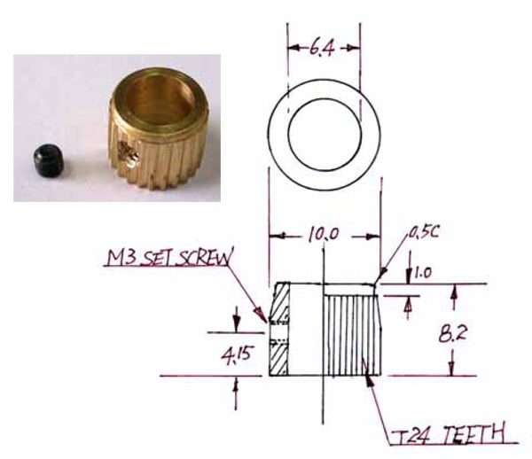
These are the same brass inserts with M3 setscrew that you find inside our high quality Davies 1900h clone knobs. They are designed for a 6.4mm pot shaft.

You can use these to make one-off or small runs of knobs out of any material you like. Wood, Sugru, 3D Printed… it’s up to you.

You could also just use them as small knobs if you like how they look. Note the screw does extend outside the body of the insert when fully tightened on a pot shaft.

Drawing dimensions in mm.

insert

Davies 1900h Clone

$
0
0

BULK DISCOUNT

| 10+  – 5% | 25+  – 7% | 100+  – 10% | 500+ – 20% |

(Bulk prices are calculated once items are added to your cart)

Pair with the new MXR knob in the same colour range

New Black 1900h types

  • Black No Line – No white line on the top. Encoder style for ‘endless’ rotary pots on digital modules.
  • Black (T18) – For 18 teeth knurled shafts such as Doepfer, Elby etc. These are pure plastic, not brass inserted.
  • Black (D) – For Make Noise, Intellijel, 4ms and many more. These are pure plastic, not brass inserted. Double check your modules actual knob orientation details before purchasing.

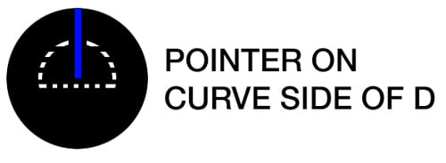
The Black (D) part has been specially manufactured to fit correctly on new style Make Noise modules. The Rogan knobs on Make Noise modules have a round hole for around 7mm of the knob shaft before it turns to a D shaft. This means that other manufacturers D shaft 1900h clones will sit no closer than 7mm off the surface of a Make Noise panel. Note the pointer orientation on these means they are not suitable for all D-Shaft pots, see diagram below, the pointer is on the curved side of the D.

1900h_D_Guide

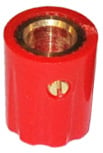
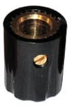
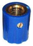
Knob_Red_IntKnob_Black_IntKnob_Blue_Int

  • No Minimum order
  • High quality brass insert with set screw (on all types except Black D-Shaft and T18 Shaft)
  • 6.4mm Shaft size
  • ABS plastic moulding

1900h_New_Black

DarkReddavies_1900h_NAMED


Synth Pointer Knobs

$
0
0

The Synth Pointer style will be very familiar to fans of Synth Tech, Pittsburgh Modular, Rebel Tech and L-1 modules. They have a 6.4mm / 0.25″ shaft with setscrew and the same sturdy brass insert as the 1900h clones.

The ‘small’ knob was previously referred to as the ‘SynthTech’ style knob.

Diameters

  • Mini – 14mm / 0.55″
  • Small – 16mm / 0.63″
  • Small Skirted – 20mm / 0.79″
  • Medium – 27mm / 1.06″
  • Large – 33mm / 1.3″

SynthPointer_Promo

Hexinverter MUTANT DRUMS Kits

$
0
0

ALSO CHECK OUT THE NEW MUTANT HOT GLUE KITS HERE!

The Hexinverter.net Mutant Drums range are partial DIY Kits which currently consists of:

  • Bassdrum – Mutant 808 Kick
  • HiHat – Mutant 808 Hihats
  • Clap – Mutant 909 Clap

The Mutant drums are modern hi-fidelity mutants of old classics with extensive CV control capabilities.

If you want a demo of the places the Bassdrum and HiHats can go, you can’t do much better than to check Surgeons recent live Modular Boiler room set which has heavy use of both.

Knobs are not included. We stock the suggested knobs for these Panels here -> white 1900h type.

The Clap set includes 6 items:

  1. Metalphoto 2 colour Aluminium Panel
  2. PCB set (3 boards)
  3. Two 4006 IC Chips
  4. All long pin female headers required

All other parts to be sourced by customer – Clap BOM and build notes here

The Bassdrum set includes 4 items:

  1. Metalphoto 2 colour Aluminium Panel
  2. PCB set (2 boards)
  3. All Vactrols required
  4. All long pin female headers required

All other parts to be sourced by customer – Bassdrum Mouser BOM and build notes here

The Hihats set includes 6 items:

  1. Metalphoto 2 colour Aluminium Panel
  2. PCB set (3 boards)
  3. All Vactrols required
  4. All long pin female headers required

All other parts to be sourced by customer – Hi-Hat BOM and build notes here

Clap Primary Features

Just like the other Mutant Drums, the Clap is a highly versatile module. It is actually a voltage controlled LFSR noise oscillator as well as a powerful percussion synthesis engine!

  • Feature-rich, analogue handclap percussion synthesis reminiscent of the 909
  • Pitch control of noise generator means you can create everything from vanilla 909 claps to broken, chiptune-like alien sounds
  • Doubles as a voltage controlled, Commodore64-sounding noise VCO via the NOISE output and PITCH CV input
  • SUSTAIN control lets you crank up the clap’s sustain and use the module as an abstract synth voice with external inputs!
  • External input allows you to synthesise claps from virtually any sound source you plug in
  • Built in internal reverb effect derived from clap tone
  • Reverb decay forms the decay of the clap sound, and is fully voltage controllable from short reverb “snaps” to long, whooshing tails!
  • You can select between internal and external noise sources as the source for the reverb sound generation, opening up really interesting sounds
  • DRIVE control lets you dial in anything from clean to extremely overdriven sounds
  • Bandpass filter cutoff control

Bassdrum Primary Features

It’s really two modules in one: a totally unique analogue bassdrum and a voltage controlled distortion module! (with the same topology as batteryACID!)

  • analogue bassdrum circuitry capable of vanilla TR-808 sounds
  • built in voltage controlled distortion (batteryACID distortion)
  • distortion accepts external inputs when not being used with kick drum (great for acid synth leads)
  • voltage control of distortion amount
  • voltage control of decay from short kicks to long “ooooooooomphs”
  • voltage control of pitch (approximates v/oct response, but not musically tuned)
  • non-invasive analogue optocouplers used for voltage control, thus, completely vintage sounds can still be had if that’s what you’re after!
  • completely redesigned, hi-fi signal chain spares no expense by replacing cheap transistor amplifiers with low noise opamp equivalents
  • you can dial in super hot, modular level output levels (up to 20Vp-p!)

Hihats Primary Features

While the internal noise generator is based on the metallic noise generator in the 808, you can plug virtually ANY sound source into the EXT input and make all sorts of cool hihats!

  • analogue hihat circuitry capable of synthesising vanilla TR-808 open and closed hihat sounds (simultaneously)
  • external audio input lets you synthesise hihats from virtually any sound source (Jupiter Storm, vcNOIZ, etc.)
  • lo-fidelity original VCAs replaced by OTA-based modern VCAs
  • VCA DRIVE control for each hihat allows you to dial in anything from soft metallic hihats to extremely overdriven, crunchy hihats
  • Exclusive switch lets you select how the two hihats (open/closed) interact with eachother when triggered at the same time
  • cutoff frequency control for internal resonant bandpass filter
  • resonant filter can be switched on/off
  • modular level mutual accent input (0-5V CV)
  • trigger input accepts almost anything as a trigger signal
  • non-invasive analogue optocouplers used for voltage control, thus, completely vintage sounds can still be had if that’s what you’re after!
  • completely redesigned, hi-fi signal chain spares no expense by replacing cheap transistor amplifiers with low noise opamp and OTA equivalents
  • – you can dial in super hot, modular level output levels (up to 20Vp-p!)


[soundcloud url=”https://api.soundcloud.com/tracks/151086003″ params=”auto_play=false&hide_related=false&show_comments=true&show_user=true&show_reposts=false&visual=true” width=”100%” height=”450″ iframe=”true” /]

[soundcloud url=”https://api.soundcloud.com/tracks/147745478″ params=”color=ff5500&auto_play=false&hide_related=false&show_comments=true&show_user=true&show_reposts=false” width=”100%” height=”166″ iframe=”true” /]

[soundcloud url=”https://api.soundcloud.com/playlists/33295582″ params=”color=ff5500&auto_play=false&hide_related=false&show_comments=true&show_user=true&show_reposts=false” width=”100%” height=”450″ iframe=”true” /]

MUTANT CLAP_quickstart_web_SMALL

Print

Print


Hexinverter Mutant Hot Glue – Full Kit

$
0
0

A full DIY kit to build this powerful 24hp mixer, dynamics and distortion station!

It includes everything you need right down to resistors, screws and power cable.

....

4 Channel Mixer with Effects Send

  • 4 input channels, each with their own level and effects send control
  • Channel A mixer bypass switch and dedicated output for easy sidechain compression
  • Channel B is dual input, but shares level/send controls (for dual output modules, like the Mutant Hihats)
  • Channel C+D summed output
  • Main mixer output normalized to compressor input

Hi-Fidelity Analog Compressor

  • Soft-knee compressor based on the same family of premium audio ICs used in some 500 Series studio gear
  • Dedicated threshold and compression ratio controls
  • Gain control dials in up to +40dB of compressor gain
  • Compressor sidechain input for pumping effects
  • ED indicator actively displays the amount of compressor gain reduction

Voltage Controlled Analog Distortion Effect

  • A classic distortion topology reborn for modular analog synthesizers and drum processing
  • In/Outputs are conveniently normalized to the module’s send and return jacks
  • Blend control lets you adjust the mix of distorted and clean input signal
  • Fast responding CV input allows for complex modulation patterns and even modulating with audio signals

The Mutant Hot Glue is a powerful bus mixer for analog effects chain design. The included high quality analog compressor offers series or parallel compression, and a sidechain input, making it well suited for drum processing. The voltage controlled distortion is based on the batteryACID: IDOW Edition design, but improved for better signal fidelity and performance. It can be used in its default position, normalized to the effects send, or like every other part of the module, broken out and used elsewhere in your modular system.

By default, the 4 channel mixer’s output conveniently feeds into the compressor’s input, giving access to easy New York style parallel compression by way of the compressor blend control. The dedicated output and mixer bypass switch for channel A allow you to easily use it as a sidechain source for the compressor. An effects send and return allow you to create complex effects routings within your modular system. With the number of excellent DSP and other effects modules on the market today, this makes it easy to combine modules to great effect, all within the eurorack modular domain.

  • 70 mA +12V
  • 70 mA -12V
  • 35 mm Depth

DOCUMENTATION

ASSEMBLY MANUAL

Hot Glue – Bill of Materials

Muffwiggler – Build Thread

Hot Glue – User Manual


Viewing all 2274 articles
Browse latest View live